
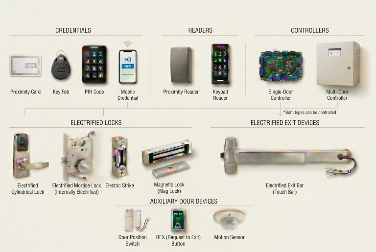
Electronic door hardware combines mechanical security with intelligent access control at the door opening, turning a simple leaf and frame into a managed entry point. It lets you control who gets in, when they can enter, and how those events are recorded, all while still relying on solid hinges, frames, and mechanical latching behind the scenes. Troubleshooting these systems requires a working knowledge of low‑voltage power, wiring practices, and how readers, controllers, and locks talk to each other and to the building’s larger security or automation systems.
If mechanical hardware answers “does the door lock and close reliably,” electronic hardware answers “who is using this door, and under what rules.” This article gives a 101‑level overview so you can recognize the main components, understand the basics of powering them, and approach common failures in a structured, field‑friendly way.
Core Components of Electronic Access Control
At a typical electronically controlled opening, you’ll find the same elements repeated: a credential, a reader, a controller (or access control panel), an electrified lock, and at least one door position or request‑to‑exit device. The credential might be a card, fob, PIN, mobile credential, or biometric—anything that can carry an identity. The reader collects that credential data and passes it along to the controller. That basic pattern shows up in almost every electronic access control system; in this article we’re focusing on the hardware at the door that actually locks and releases the opening.
On the locking side, there are a few common hardware types you’ll see over and over. Electric strikes replace or supplement a mechanical strike and let you release the latch electrically while still using standard locksets on the door. Electromagnetic locks (mag locks) hold the door closed with electromagnetic force and release when power is removed or a control signal is given. Electrified mortise and cylindrical locks build the electronics into the lock body or trim so the opening looks more like a typical mechanical door from the outside. Wireless locks package the reader, lock, and often the controller into the trim itself and communicate back to the system over a wireless network instead of long cable runs.
Electrified exit devices add two more common options at the door. Electrified trim controls the lever on the pull side of the device, locking or unlocking the trim electronically while the push pad still provides free egress. Electric latch retraction (EL/ELR) uses power to retract and often hold back the exit device latch bolt so the door can act like a push‑pull opening while still providing latching and panic hardware when power is removed.
The controller is the decision‑maker. It checks the credential against stored permissions—who can use this door, at what times, and under what conditions—and then tells the lock hardware to unlock if everything matches the rules. Door position switches and request‑to‑exit (REX) devices provide status and egress information, helping the system know whether the door is open, closed, forced, or someone is legitimately leaving.
Behind all of this is the management software or cloud platform that stores users, schedules, and event history. From a field point of view, your first step is usually just to identify each device at the opening and confirm that they’re all connected to the same “story”: the same controller, power supply, and intent.
Low-Voltage Power and Wiring Standards
Most electronic door hardware runs on low voltage, commonly 12 or 24 VDC. Power may come from a dedicated access control power supply, a fire‑rated power transfer, or a shared panel feeding multiple openings. Properly sizing that supply means accounting for the current draw of each device—locks, readers, controllers, sensors—and adding margin for inrush and future expansion.
Wiring needs to follow both electrical codes and manufacturer recommendations. Conductor gauge, cable type, and run length all affect voltage at the lock head, especially on long cable pulls or when multiple devices share a pair. Voltage drop is a common culprit when devices behave inconsistently: the system may look fine on paper, but the actual voltage at the strike or mag lock under load is too low for reliable operation.
Good practice includes labeling conductors, separating power and data where required, and following color‑coding standards that match your shop or the project spec so future troubleshooting is easier. Keeping terminations neat and documented may not feel urgent during installation, but it pays off every time you have to diagnose a problem a year—or five years—later.
“Fail‑safe” and “fail‑secure” describe what the lock does when power is lost. A fail‑safe lock unlocks when power is removed, prioritizing life safety and ease of egress; a fail‑secure lock stays locked on the secure side when power is removed, prioritizing security so power is only needed to unlock it, not to keep it locked. In practice, exterior and high‑security doors often use fail‑secure hardware for perimeter protection, while some doors on egress routes or in certain life‑safety applications may require fail‑safe or a combination of mechanical egress with electrified control from the secure side, as influenced by building and fire codes.
Voltage drop is the loss of voltage as current travels through wire; longer runs and smaller gauges increase resistance and reduce the voltage that actually reaches the device. Basic calculations multiply current by total circuit length and conductor resistance to estimate loss, but most installers rely on manufacturer tables or online calculators where you enter wire gauge, distance, and current draw to see if the device will still be within its specified voltage range. If it will not, the usual fixes are using a larger wire gauge, shortening the run, moving the power source closer, or, where appropriate, using a higher supply voltage with compatible hardware.
Yes, but the integration has to be designed so life safety comes first. Many jurisdictions and standards expect certain electrified doors to unlock or remove power to specific locks—especially mag locks—on fire alarm so occupants can exit and first responders can enter where required. Common methods include fire alarm relays that drop power to fail‑safe locks, release mag locks, or signal the access control system to unlock designated doors whenever an alarm condition is active. The exact approach depends on lock type, building design, and local code interpretation, so coordination between the fire alarm contractor, access control vendor, and AHJ is essential.
Intermittent issues—locks that sometimes don’t release, readers that randomly reboot, doors that only fail under certain conditions—are often caused by marginal power, loose or damaged wiring, or environment‑related factors rather than a single “bad” device. A structured approach starts with checking stable voltage at the device under load, verifying polarity and terminations, and then separating hardware from logic by testing outputs directly from the controller. Temperature swings, door movement, and other equipment cycling on the same circuit can all contribute, so documenting when failures occur can point to the real cause more reliably than replacing parts at random.
Electric strikes work well when you want to keep a conventional mechanical lock on the door and control access by releasing the latch electrically at the frame, often with good retrofit flexibility. Mag locks provide strong holding force and simple wiring at the head of the door but typically require additional egress and fire‑alarm interfaces, and they rely entirely on power to stay secure. Electrified mortise or cylindrical locksets (and wireless locks) put the electronics into the lock or trim itself, keeping the opening looking more like a standard door while integrating more tightly with the access control system—often a better fit for interior and appearance‑sensitive doors.
A door position switch simply tells the system whether the door is open or closed, which is essential for monitoring door‑held‑open or forced‑open conditions. A request‑to‑exit device signals that someone is legitimately leaving—via a motion sensor, push button, or handle contact—so the system can momentarily unlock or ignore alarms for that event while still logging it where needed. Using both allows the controller to distinguish between normal egress, access, and forced or propped conditions more reliably.
Final Thoughts
Electronic door hardware adds intelligence and control to the basic mechanics of a door, but it also adds complexity. Reliable performance depends on solid mechanical foundations, correctly sized and distributed power, clean wiring, and thoughtful integration with access control and fire alarm systems. All of this assumes the underlying door, frame, and mechanical hardware are installed correctly—electronic hardware can’t compensate for a door that doesn’t close or latch the way it should.
This introduction is meant to give you a mental map of how the main components fit together and where problems typically show up. Each topic here—component selection, power design, wiring standards, and systematic troubleshooting—can be explored in more depth as you encounter real projects and issues in the field.